Lab 0xFF Ball Balancer Term Project
Ball Balancing Platform Summary
This project is the culmination of all the previous labs, using a little bit from every one. The goal of this project was to get a platform to actively balance a ball using an outer loop controller that sent reference position data to an inner loop controller which could then balance a ball by controlling the motor duty cycles of the motors on the x and y axes. Unfortunately, we were unable to tune our ball balancing platform to a point at which it could successfully balance the ball, but we got the platform to respond correctly to the position of the ball on the platform. The platform also successfully balanced itself when there was no contact with the touch panel.
Balancing Platform Design Overview
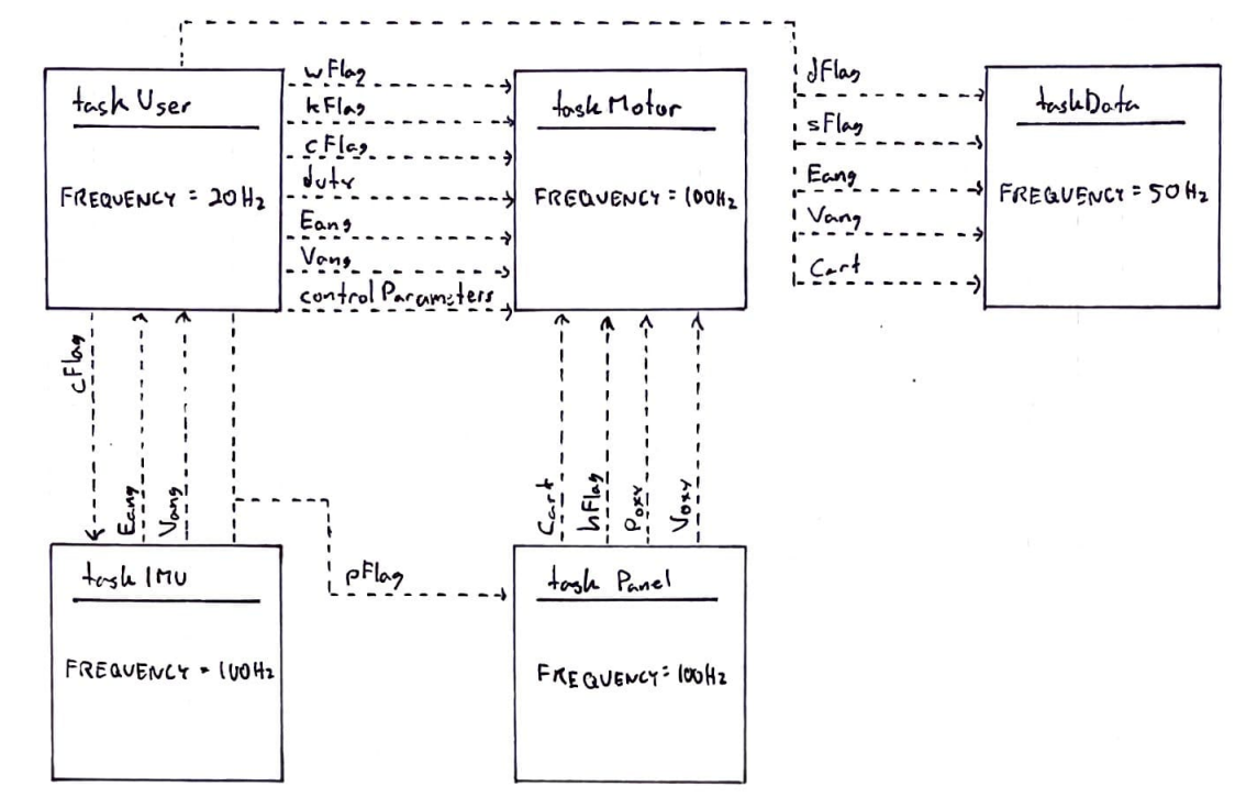
Our ball balancer runs using cooperative multitasking with time slicing to switch between the five task files that we use. The first file, taskUser, essentially runs as a command task, running all of the user interface and reading all the user input commands. This task then dictates what to run in the other tasks accordingly. The next task, taskMotor, controls the motor duty cycles and runs the closed loop control on the platform's x- and y-axis motors. It is able to change the gain coefficients and toggle the closed loop control on and off, also knowing when to run both outer and inner loop control or just inner loop depending on whether there is contact with the resistive touch panel. The third task, taskIMU, allows for the connection of the board microcontroller with an IMU placed on the platform, which will then read the angle and angular velocity data from the IMU for use by the rest of the tasks. Similarly, taskPanel connects a resistive touch panel with the microcontroller, which then reads the x and y positions and velocities of the ball on the panel for use in the closed loop control. Finally, taskData is in charge of reading this data and writing it to files when told to by taskUser.
Follow these links to see the full documentation of each of these tasks.
- taskUser_F
(https://lmurray03.bitbucket.io/task_user___f_8py.html)
- taskMotor_F
(https://lmurray03.bitbucket.io/task_motor___f_8py.html)
- taskIMU
(https://lmurray03.bitbucket.io/task_i_m_u_8py.html)
- taskPanel
(https://lmurray03.bitbucket.io/task_panel_8py.html)
- taskData
(https://lmurray03.bitbucket.io/task_data_8py.html)
Here is the complete task diagram of how each of the tasks interacts with each other.
One of the cooler features of the platform is that when calibrating the touch panel, the panel will respond with a small amount of haptic feedback when done calibrating at each position. The rest of our ball balancing platform features can be seen below in the sample puTTy windows and in the video.
Balancing Platform Control Overview
Our ball balancer functions using an inner and outer loop controller. The outer loop controller takes the reference position of the ball on the platform (always equal to zero) and subtracts the actual position of the ball, multiplying it by the proportional gain to make the proportional controller. It then goes through a derivative gain to finally output the reference angular position needed to return the ball to zero. This reference angle goes through a saturation limit, keeping the absolute value of the max angle under 10 so that the ball doesn't go flying. This filtered angle then goes through the inner loop controller with similar proportional and derivative control, outputting the motor duty needed to return the ball back to the center of the platform. This motor duty output also goes through a saturation limit, causing the max motor duty coming from the controller to be less than the 40 or greater than -40. Integral gain is not included in the control since it was causing issues with the balancing.
Example PuTTy Windows
To demonstrate the full functionality of our user interface, the PuTTy windows after each input is shown here.
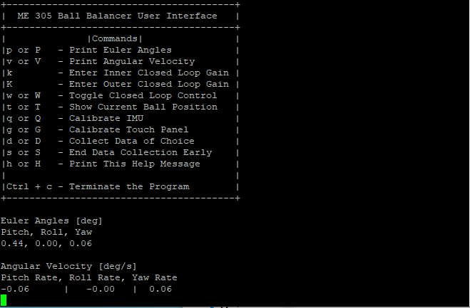
This image shows the full user interface along with each of the possible commands that a user can put in. Below the command panel, after pressing the keys "p" and "v", the PuTTy window will show the euler angles and angular velocities of the platform's current orientation. At the time these commands were called, the platform was balanced and not moving, hence the close to 0 values for each.
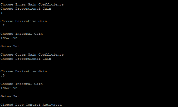
This image shows the PuTTy screen after changing the gain coefficients for both the inner and outer loops. As you can see, our integral gains are deactivated for this ball balancing project because our platform balanced the ball better without it.
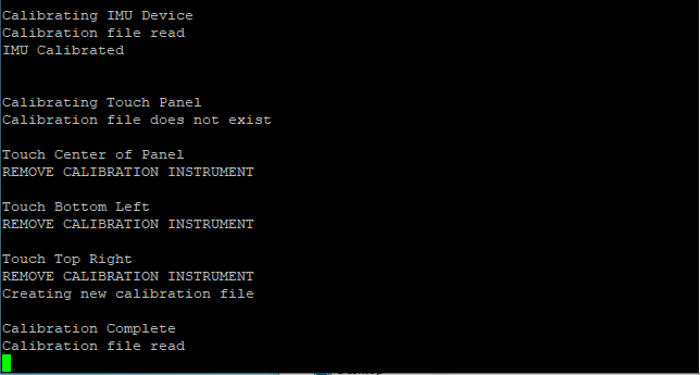
This image shows the PuTTy screen after both the IMU and touch panel calibration commands are called. The IMU was already calibrated, so it shows that the calibration file was read from, but the touch panel still needed to be calibrated, so it shows the process of how that is done.
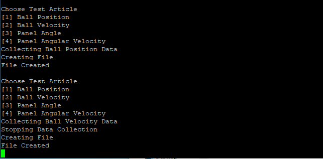
This image shows the PuTTy screen after collecting a full 20 seconds of data and after stopping the data midway through collection. They are fairly similar, stopping the collection early merely prints out a stopping message.
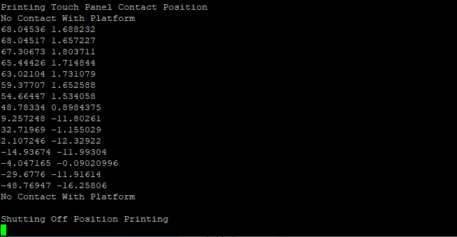
This image shows the PuTTy screen after using the show current ball position function. As you can see, the function does nothing until there is contact with the board and then it will print out where it is in millimeters away from the origin. It then turns off again when contact with the platform ceases.
Resistive Touch Panel Object
The touch file instantiates a resistive touch panel that can measure the position and velocity of a ball along its surface. It also allows for the calibration of the device to ensure the platform is reading corrected position and velocity values.
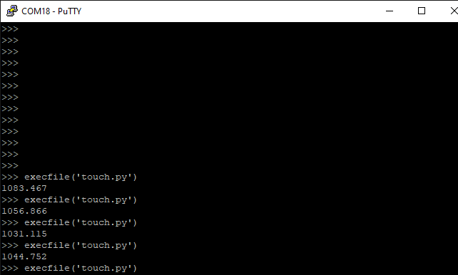
To verify that our three scans could run sequentially in under 1500 microseconds, we ran all three 1000 times and averaged the time it took. Our three scans took around 1050 microseconds to run each time, staying below the requirement.
Please see https://lmurray03.bitbucket.io/touch_8py.html for more details on the touch class.
Video Demonstration
Please click the link below to see a video demonstration of how our ball balancing platform works
https://drive.google.com/file/d/1KllZbFO3XsMIUkkP-je4vUoZPuBxSWUV/view?usp=sharing
- Date
- March 18, 2022