Lab 0x04 Closed Loop Speed Control
Closed Loop Controller
The closed loop controller made for this lab works by instantiating an object in the motor task and using the motor task to update and run the closed loop control with the same timing as the other tasks. Our closed loop controller only works with a proportional gain as of now, but we plan on adding in functionality for an integral control gain later on. Adding in closed loop control required the addition of a few states in the user task to allow the user to interface with the new capabilities of the microcontroller.
Tuning Plots
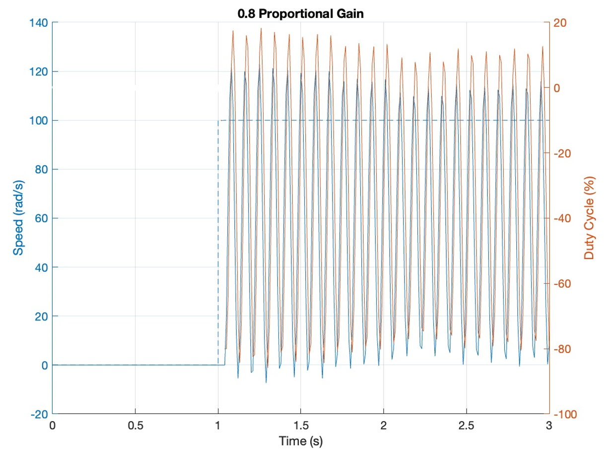
For every test while tuning our closed loop controller, we kept the reference velocity at 100rad/s to get consistent results. We initially tested our closed loop control response at a gain og 0.8, and we got violently oscillating behavior in the motor as seen below.
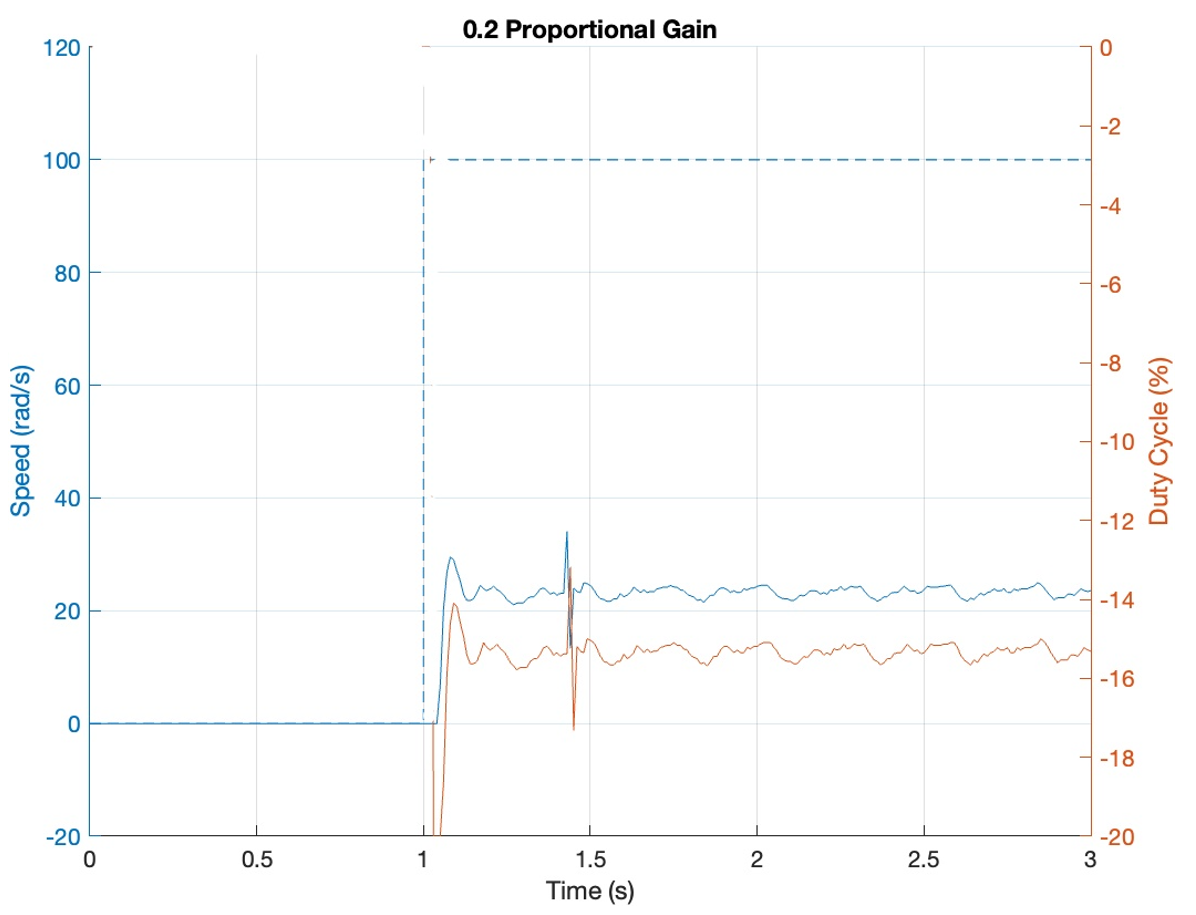
To reduce this large oscillating response, we reduced the proportional gain down to 0.2 which did successfully reduce the large oscillations, but it led to very jerky behavior.
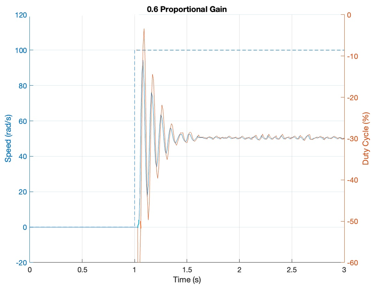
We then increased the gain to 0.6 to see if we could get a non-jerky response with less oscillation, and 0.6 successfully gave us that while reaching about 50% of our desired motor velocity at steady state.
To see if we could improve the response at all, we dropped the gain down to 0.5, which reached steady state quicker with less extreme transient oscillation, but it settled at a slightly lower velocity of around 45% of the reference.
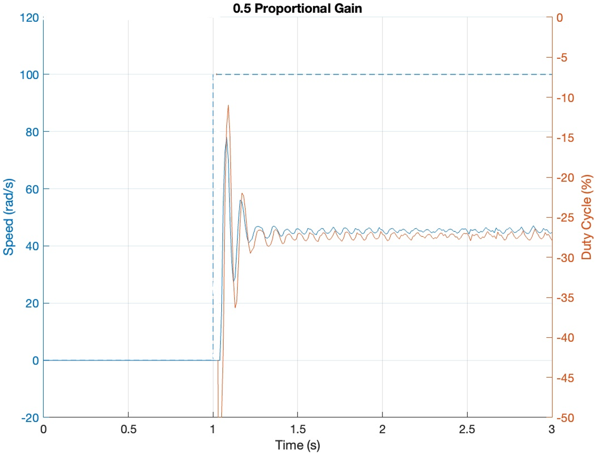
From our plots, it seems that depending on the constraints our system was under, we could choose between the gains of 0.5 and 0.6, depending on whether more overshoot was okay if the reference velocity is closer like we see with the gain of 0.6, or if overshoot is something we are trying to avoid in which case 0.5 would be a better choice. We see the massive error between our reference velocity and actual velocity because proportional gain control is not particularly accurate on its own, and when we add in integral control later on, we will see far better responses from the motor.
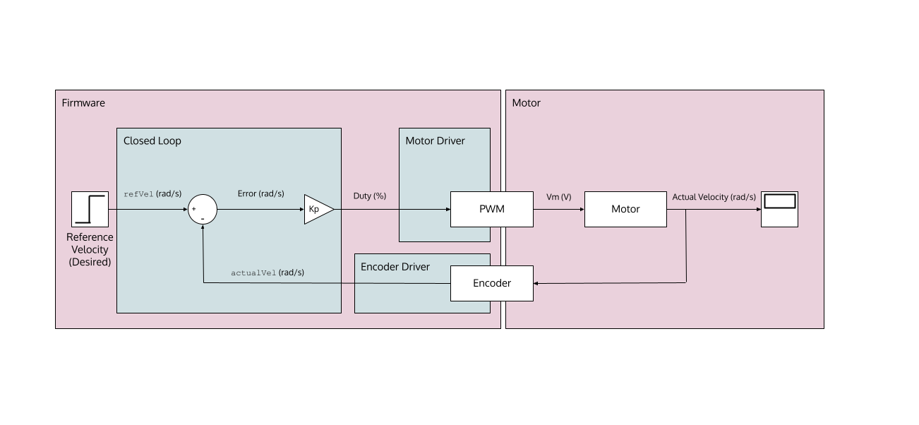
Block Diagram
Below is a block diagram representation of our system, showing how the closed loop feedback is sent back into the motor driver to change the duty cycle, which then in turn feeds back in, hence the name closed loop control.
Closed Loop Control Object
The closed loop control file instantiates a closed loop controller object inside the MCU. This closed loop controller object allows the usage of a proportional gain with a set reference velocity to constantly update the duty cycle of the motor to reach that speed.
Please see https://lmurray03.bitbucket.io/closed_loop_control_8py.html for details.
Edited Lab 0x02 and Lab 0x03 Files
While creating the new lab 0x04 files, we added to and edited the following files from lab 0x02 and lab 0x03, changing the code and remaking the state-transition and task diagrams:
- taskUser
(https://lmurray03.bitbucket.io/task_user_8py.html)
Added the closed loop controller functionality required for lab 4, adding a few states
and expanding our command and printing states.
- main
(https://lmurray03.bitbucket.io/main_8py.html)
Added a few shared variables needed to use the set gains and reference velocities
across the motor task and user task.
- taskMotor
(https://lmurray03.bitbucket.io/task_motor_8py.html)
Added the closed loop controller functionality into taskMotor to constantly update the
duty cycle when the closed loop control is activated and to avoid creating a new task